Ported Throttle Body

This damn car is like my extra girlfriend – I just get things squared away and it’s driving great, mileage is back up, then BAM!! I’m so frustrated, I just cleaned the throttle body, now I’m still getting strange revs up and down, inconsistent engine throttle, loss of engine rev in neutral, and idles up to 3000 RPM. I pulled the hot side pipe off of the throttle body and bought throttle body cleaner, but it looks like that’s not the issue. The thing is so clean I could eat off of it. I guess the stupid car needs a throttle body now. Shit!

At first, the throttle body error light would reset after a restart, now it will not. I guess it was going out slowly, much like my patience. My Corolla doesn’t do this crap, neither does my Yukon. Ugh. I guess I’m riding my bike all week. I cannot get any of my sockets to fit on this nut (the socket walls are too thick.) It is bigger than 10mm, seems like 7/16″ which doesn’t make any sense. I added the Cravenspeed Spacer last year, and it was the worst getting it off and on. Does that spacer come with different size nuts? Reading other posts, it seems like it was a T30 but mine is clearly not that. I can’t get the stupid nuts loose to save my life… Anyone want to buy a Dart?

OEM Throttle Body:20160805_083250
20160804_193944
20160805_180051

Replaced the throttle body. Interesting to note, the new part was ultra easier to work with from my original. The wrench and socket fit over the new TB just fine, and it was indeed a 7/16″ socket, which came with the Cravenspeed spacer. I put the MPB bored throttle body on as a replacement, as I got it used for cheaper than an unaltered OEM one. This did not fix the issue. I removed the accelerator pedal, still the same P2135 code. Taking it to the shop. (It was a wiring issue in the Unichip harness)

Tags:
Categories:

Boost Leak Confirmed

Note: On Saturday, July 30, 2016 I found the issue with my gas mileage. Sweet lord, what a relief! Driving up to a friend’s I got over 36 MPG, and it was b/c of multiple boost leaks. I had one leak on the intake, so we pulled it and added a sealant and re-tightened. The other side of that same line, near the oil separator had the rubber “L” piece ripping a bit, causing air and some oil to leak out. The biggest leak was between the downpipe and the turbo – whoa! We pulled the bottom loose, and removed the metal bracket that attached the factory DP to the exhaust. This allowed it to move up another few millimeters, making a tighter seal and fixing the leak.

The last leak was between the Forge BOV and the GFB DV+. Keep an eye on this one, as I had it installed properly, but we were still getting a tiny leak under high pressure. We added some high-temp silicone to seal this off, and used shorter bolts without washers, and tightened the crap out of it. Voila!

Also on the list, my two rear tires are total garbage. I got Delinte tires when I bought the wheels, and although they are all weather tires, they were total garbage. The front two blew already last year, which I replaced, and now the back two, each have a bulge in them that you can feel rolling along the highway. I ordered more tire stickers, and new tires.

Pic has nothing to do with this, it’s just an excuse to show off my demon eyes! Lol. (I’m getting the laminate replaced tomorrow)

Tags:
Category:

Headlights, Demon Eyes, Halo Headlights

Next Up: Headlights!!!! Woot Woot! Bake these bad boys for 10 minutes at 220˚ – Shazam! They open right up. Do not attempt with OEM Chrysler headlights, the adhesive is heat resistant and needs to be cut open.  Some aftermarket headlights may change the bulb socket, so be aware of that.  Mine are EagleEyes brand, and they now use an H8/H9/H11 bulb, instead of the Dart’s 9012 socket.
20150402_134325
20150605_082953
20150605_083002

OEM Silver Headlights:20150321_164658
20150405_201514

Painted the silver portion of the headlights gloss back, and also used the 2k Glamour Clear Coat. The pic also shows the demon eyes (partially) installed. I used a dremel to cut away enough of the headlight to fit the halo in, as I also used a diffuser, so you don’t see the naked LED strips.
20160706_004756
20160705_004624
20160709_094116
20160709_094127

I’ve got a lot of mods to do, if I want my build thread as long as @viperman96 … Lol. That being said, this project started as a simple repair. Last year, I installed my FMIC, and has been working great. A few weeks ago, I was taking a friend home after the Guns N’ Roses concert (BAD ASS, btw!) and on the way home, I heard a “pop.” I’m not sure what was up, but I was pretty sure something blew off. Sure enough, upon further inspection, my pipe blew off the driver’s side of the FMIC. DAMN!

I put her up on the Yoderian ramps, and had a look. I tried every form of yoga, stretching, contortion, and hypnosis, but I could not reach up into the area to fix it. At that point, I said screw it, and pulled the fascia off. I wasn’t ready to do the headlights, and other wiring I had been putting off, but at this point, I didn’t want to keep pulling it off. Once I got in there, I realized the hood latch bolts had come loose, and the FMIC fell forward just enough to pull it loose. I re-bolted it and used toothed lock-washers. That thing will never come out, again.

Here are some pics of the wire mess before I cleaned everything up. I went through an soldered, crimped and waterproofed every single connection. I also soldered on loop fasteners to all of the ground points. I even sanded down a few areas to make more solid ground connections. This proved to be totally worth it, as the cheap HIDs that used to flicker (just a tad) were now completely solid. Perhaps this is the only case of flawless, non-canbus lights, that I have seen, although it’s taken me a bit to finally get them perfect.

soldering the connections:20160706_004651

adding loop fasteners to the ground points:20160706_203116

Moved the (hot) resisters to below the intake and fascia, routed wires to the underbody lights:20160706_004708
20160706_004715

OMG – what a mess!20160706_004651

re-routed all of the wires under the fuse box (had to remove it):20160706_004738

added tie wraps (replaced them with black, later):IMG_20160708_170415

tie wraps (again, I could see the yellow through my grille, so I swapped them with black (doh!):20160706_203105

Almost back together:20160708_081451

Since I swapped out the battery for an Optima, it gave me the chance to put all of the auxiliary power on the side terminals, leaving only critical engine components on the top terminals. I may add a dry cell battery for car shows, as well.20160708_081506

After the front end was re-assembled, I put all of the control boxes along the passenger side under the hood. There is a ledge with plenty of space – All of the boxes got adhesive promotor and 3m adhesive. They are all RF controlled, and when the hood is open, I can read what mode / setting they are in, and adjust accordingly, if needed. This now includes the Starry Night Halos (https://www.starrynighthalos.com/ or Herculeds. The most powerful name in LED lighting.) Demon Eyes* and Yoderian Magical Underbody Lights.

[IMG] Angel Eyes, also known as “halos,” are accessory lights that are installed or integrated into a vehicle’s headlight assembly, to encircle the low or high beam headlight. They do not replace the headlight or any other lights, they are simply accessory lights, for cosmetic purposes, or to be used as a DRL.[/IMG]

These are the wires coming out of the headlights. All of the connections were waterproofed, as well, which I highly recommend. The Starry Night Halos DO NOT come with enough cable length to mount in a logical position, which was really annoying. I had to solder extensions on them.

20160708_200123

Here is the headlight assembled. You can see the halo diffuser in this pic with the lights off.
20160912_082714
20160812_211826
20160825_225642
IMG_20160824_235739

Here are all of the interior switches – the four colored switches are for interior and exterior lights.  The smaller, metal switches are Grille/Underbody Lights, SN Halos, and Demon Eyes, respectively.

20160701_171357
20160710_204820
20160710_212400
20160712_224843
20160715_200821
I would also like to point out to the next guy trying this – the Dragon Laminates (Dragon Eyes) baked in the oven @ 220˚ for 10 minutes with no issues, whatsoever.

*Angel Eyes, also known as “halos,” are accessory lights that are installed or integrated into a vehicle’s headlight assembly, to encircle the low or high beam headlight. They do not replace the headlight or any other lights, they are simply accessory lights, for cosmetic purposes, or to be used as a DRL.

Tags:

LED Lighting, Dream Color Underglow Lighting, Wheel well Lighting, Strobe Lights

Started out with blowing off one of my pipes connecting the FMIC – before I knew it, she looked like this, again:20160706_004651

Next installment, interior switches and wiring. I ran all of the needed wires through the firewall, both below the clutch, as well as on the passenger side, behind the glove box. I did the project in phases, as there is never much time in my life, nowadays. I pre-wired all of the switches in my shop, and measured out all of the cable runs, leaving the excess at the interior firewall. Most of the wires could be run by simply removing the lower footwell panels and below the steering column. Here are the pre-wired switches, and the holes already drilled out. Everything was trimmed and heat-shrinked prior to the installation in these pics:
20160701_171404
20160701_171357

The wiring is a bit more complicated than needed for most, but it is my specialty, and this is for car shows and hang-outs. The first four colored switches are simple on/off, controlling the strobe lights outside, the KITT LED lights, interior roof shadow lights, and the console and glove box lighting. The second set of switches are DPDT switches, or on-off-on. These are wired to two separate power sources. Up is on constant, with power straight from the battery. Middle position is off, and the lower position is on with an ignition switched fuse location. This enables the exterior LED lights, and the Halo headlights and demon eyes to come on with the car, but also enables them to run with the car off and locked.

Tags:

Seafoam Cleaner, throttle issues

It’s been too long, guys! I recently had the car apart for a week, and just went nuts. Started with a simple repair (pipe blew off the FMIC) and then once I had the fascia off… it was all over. Updates to come in this crazy thread. I’ve got to uphold my 2016 Ride Of the Month status! Lol. Anyway, I had a throttle body error code a few weeks back. The solution, guys, is to clean out your throttle body! Before I committed to the knuckle-busting task, I tried using Seafoam. I sort of made an injector bottle out of a water bottle, some mulit-pair cable heat shrink, and some zip ties. I could then inject this into the pipe, just before the throttle body. Otherwise, it would spray out when holding the RPM up to avoid choking. I did this a couple of times and it completely went away, and worked like a charm. Looked like a smoke-screen, and I only used about 1/3 of the bottle.

The issue ended up being a wiring issue with the Unichip harness.  Two of the lines shorted, so I soldered two jumper connections, and added waterproof connectors, so the whole thing could easily be removed.

Tags:
Category:

Electric Exhaust Cutout and Custom Midpipe / B-pipe

Exhaust cutout installed today!  This is an electric cutout, that dumps straight out of my down pipe, and then to a custom 2.5″ midpipe / B-pipe.  Switch is installed next to shifter.Name: ForumRunner_20160606_102413.png Views: 112 Size: 406.7 KB

I had a custom 2.5″ B-pipe created, and welded on a cutout, right after the downpipe. I installed the switch inside, near the shifter, but out of the way of the seat. Only takes a second to open and close – sounds awesome! It moves the power band up, so the turbo kicks in smoother, and screams up top. There is a little bit of low end torque lost, similar to those with a 3″ exhaust, but makes it up above that. I wish the pics were a bit better, but whatever. It exits out of the front hole / door in the underbody aero panel. It was open for over a full tank of gas, no issues. I was going to add a tip, but it’s too low.
20160606_104615
20160606_104625
20160606_104639
20160606_125032
20160530_135252

I cut this out for a tip, but never installed it. #lowlife  The above hole was later cut a bit larger, as I sometimes shoot flames!
20160627_215417
20160627_215434

This is how I soldered the switch. This switch is a momentary on/off/on switch. Forward is open, back is piped exhaust, tied to ignition switched power.
20160701_171351

I purchased the electric cutout kit from ebay, and it was about $85.  Here is something similar.  It is a basic 2.5″ cutout, that includes cutout, switch, wire, gaskets, y-pipe, clamp, dump, and hardware.  The midpipe is fine, running closed, for emissions in IL.  The high flow downpipe, however, was not, and has to be removed every two years to pass emissions.

Here is the final installation pic – It is the silver switch, to the left of the gear shifter:20161010_224301

No codes, or issues, however, if you run the cutout open for a long time, especially under WOT, you may get an error for rear O2, although it hardly comes on for me.  I ran her on the dunk, and open and closed was very close, although open gained 2-3 more whp.

Tags:

Rear Engine Mount

Most guys have done this first, I guess, but I was hesitant to do it, but it’s not bad. There is a bit more vibration, especially when the AC is running at idle, but I found out the sound system has an off switch! Once I had the music back on, couldn’t tell the vibes unless AC on at idle. I do feel the wheels spin easier, and seems to be more responsive. At the same time I did the rear engine mount (flex, in orange) I also did the CDV delete. My full review of that is here.

This is the stock OEM mount next to the Deyeme Racing Flex mount:20160530_133544
20160530_133136
20160530_134807
20160530_135244
20160530_135259

Tags:
Categories:

CDV Delete and Review (RRM / Road Race Motorsports)

Review of the CDV Delete from Deyeme Racing

First of all, let me preface this with saying I am no car expert, but I have learned a lot the past 18 months with my Dart. The only thing I can offer is my personal experience, and I hope it helps somebody else out there. My inbox, as well on FB, has been blowing up with people asking about this, so here we go:

I did this installation during the afternoon, after installing the flex rear engine mount, which came in the same box from @DeyemeRacing . I guess I’m their poster-boy this week – lol. I had some prior issues, which is relevant to the topic, so I’ll explain. I bought the Dart last Feb 14 – and the night I brought it home, my clutch sunk to the floor and stayed there. Looking back on the situation, it actually stuck a tiny bit a few times, but I didn’t know enough to recognize it, as it was very subtle. The following week, the Kia dealership, where I purchased the vehicle, replaced the Master and Slave cylinder, as well as the clutch. They tried to blame my driving on the clutch going out – yeah – on the first day I owned it. Anyway, you don’t mess with a Amish guys’s kid – needless to say, a year later Chrysler reimbursed me for everything. Woot Woot!

As time went on, after the replacement, I had 2-3 issues over the next 8 months, where the clutch would stick momentarily, and then pop up. Couldn’t get any video, but I took it back in one time, complaining of the same issue, they couldn’t replace it and claimed to bleed the clutch. It did feel better, and I know they bled it b/c the green outlet nipple was missing (no cap.) As time went on, I would try to analyze the clutch, and I realize that many, if not all, of the “jerky” launches I had in first gear was due to the CDV sticking, ever so slightly, then releasing a moment later, causing a less than perfect launch. I have been driving stick for over 25 years, so I’m pretty confident in my ability to drive any stick, even bigger trucks. If I needed to move quickly, such as WOT, the clutch would stick momentarily. I also noticed (as others did) that on my WOT launches, I would grind third gear. It happened about 5-6 times since I’ve had the car, no more, but it was odd to me.

I also agree with others about the 1-2 shift point. Let me tell you what – this freakin sh!t fixed everything!!  Buy it and get out of here! Go!

What are you still doing here? Ok fine:

Does this feel like a new clutch?
No.

Does this feel stiffer?
Yes, but that may have been accomplished by simply topping off the fluid levels. The clutch feels tight and consistent.

Did I have to re-learn the clutch?
No.

How long did the install take?
2 hours.

Did it change the way I drive?
No.

Does it make me happy?
OMG – Every single launch was perfect, even in slow, city traffic. I have not opened it up yet, I’ve only driven 10 or so miles in city traffic, but A LOT of clutch holding, launches, downshifting, etc. Shifting into second gear was perfect every time. I had no jerkiness, no sticking, no issues, and I couldn’t be happier. I don’t double clutch much in this car, but I do rev match to downshift, and there were no issues there, either – smooth as butter!

This fixes the inconsistencies of the CDV. I really think many Darts’ CDV’s stick a little bit, but so slight that you don’t always notice, until it’s gone. I didn’t have to adjust anything, and driving it was as easy as driving any manual. Also, keep in mind, I never really had issues launching, but looking back, I can see where it was less than consistent. I would say, that if you haven’t done a bunch of mods, this is NOT the easiest installation. The biggest difficulty was bleeding the system.

Two issues I had while doing this installation was removing the CDV without pulling the pushpin completely out. I dropped the pushpin, and it’s very difficult to see in there, so be careful of losing it. The other issue was my air compressor wasn’t powerful enough to use the brake bleeder tool. That fluid drained SOOOO slow. I ended up using a friend to help, so one could pump the clutch and the other monitored the fluid. The biggest thing, is DO NOT LET AIR INTO THE SYSTEM. Make sure fluid stays in your supply tank. I’m not sure if I read it wrong, but I bought 3 quarts of brake fluid, but only needed less than one. It was taking so long to bleed, I ended up topping it off and replacing only what I needed. I’m going to see how it does, as I haven’t opened the other two bottles, but by looking at the tank, I don’t think you could even fit more than a quart in there, but I could be wrong.

I will give more results on the power / racing side on my personal build thread here. I will surely beat my 7.16 second 0-60 now that my clutch responds properly.

If you are in Chicago, New Star Transmission will install it for you for $140 + parts, if you don’t feel confident in your abilities. PM me for details, or google them – ask for David.

OEM CDV:20160530_233527

Tags:
Categories:

How to Build and Install a Custom Front Wind Splitter / Front Lip / Diffuser / Chin Spoiler

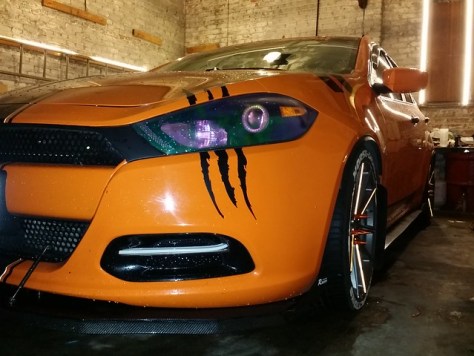
Custom DIY Front Splitter / Chin Spoiler / Front Lip / Ground Effects
IMG_20160428_003030The Mopar lip kit is fine for most people, in fact, it looks quite nice. The problem I had is the cost, and the fact that everyone has that one option. I have done a ton of research on splitters, lips, spoilers, etc., but I am in no way a car, or racing expert. Use my instructions as a guide – then put your own flavor on it. Not everyone will like this style, but you can see what I struggled with, and why I made the decisions I did. I hope you like it, but if you don’t, you can build yours any way you want.Before you ask, a front splitter is designed to produce extra downforce at high speeds to the front wheels for better handling and traction. These are often used in conjunction with rear spoilers in race cars, and won’t have much of an impact on driving below 80 MPH. They usually fill the bottom portion of the car from just ahead of the front wheels to a few inches beyond the front of the car. Oh, and they also look freakin’ baddass!Typically, a front splitter should fill in the entire space in front of the wheels, and should not have any spaces or openings. My Dart has the Aero package, which means it is already covered under the entire bottom. It also means the aero panels protrude down past the fascia. If you put a flat piece of material under the whole thing, it can’t touch the sides b/c the oil drain area sticks down too far. A splitter should also be flat if possible, so I omitted the center area in the splitter, and left it as is. This also reduced the weight of my entire splitter to less than 3 lbs.Now the question everyone asks (go ahead): What’s it made out of? Alumalite. “Alumalite is a strong, aluminum composite panel made of with a high density corrugated polyallomer (CPA) core that will not swell, corrode, rot, wick water, or delaminate even under prolonged water exposure. Factory-baked polyester painted aluminum faces add high gloss brilliance and rigidity.”There are many ways to do this, and the cheapest would be plywood, and then covered in polyurethane resin to make it waterproof. The problem with this is weight. ABS plastic is also pretty expensive, and also heavy. I looked up what the professional racers use, and most of them are using some form of alumalite. It is incredibly strong and lightweight. It can also be bent, if needed, and is completely waterproof. The best way to describe it is two, thin aluminum sheets, separated by a corrugated material.
20160310_143825So then I researched, “Who else would use Alumalite,” and I found they use it to make signs! I reached out to some local sign companies and confirmed this. All you have to do is ask them for scraps. I needed something that was at least 72” x 26” – I ended up finding a piece for the price of a 12-Pack of Anti-Hero IPA (although he is my buddy, and did the graphics for Dartlene Orangina)
20160308_201807
20160310_194925
20160310_194934The first thing I needed was a template, and a way to line things up. The easiest way to do this was to start with the Mopar Front lip. When tracing the lip, you have to be careful, and take into account the 7/8″ rise in the middle of the fascia. If you press the lip flat and trace it, along with the holes, once you hold your trace up to the car, you will find the outer edges and holes are too wide. Be careful to trace the piece while keeping it’s shape, holding the edges up.
20160315_011531
20160313_171527I followed the front angles of the car, but I wanted a little more aggressive appearance. I also knew that I wanted to wrap the thing in carbon fiber, and if you’ve done any wrapping, you’ll know how difficult it is to wrap around a curved edge. If you want to try this method, you’d have to cut along the top edge, and use a separate piece for the front / bottom. I used cardboard to create my original template, so I could mess with it, as well as hold it up to the car for rough placement. I was concerned the cardboard would bend, but the final material would not, so I also had to keep in mind the upward arch in the middle if it is attached flush to the fascia.
20160417_134220
20160417_134231
20160417_134353Now that I had my template, I dry fitted it to the car to make sure. Then I traced it onto the alumalite, and cut the front shape and the inner circle, leaving a bit extra on the inside, which could be trimmed. As it was, I had to adjust the holes a little bit after the final cut, as I was using the same holes to secure the aero panel and the Mopar front lip, if you had one. The 4 screws in the rear connected perfectly to the cut splitter, but it had to bend up too much in the middle to work, so I needed spacers. I took some brass tubing I had lying around, and cut it into (4) 7/8” pieces. Then I sanded and painted them black. Washers were used above and below the splitter and spacers, and I found some wood screws that matched the thread of those metal clips in the aero panels. Lock washers were put on the very bottom to secure it.This is without the spacers:
20160417_144829
20160417_144836
20160417_144841
20160417_144948
20160417_144958
20160417_170311

Spacers:
20160424_190539
20160424_190543

Underneath the spacers:
20160424_190552
20160424_190556

Then I wrapped the splitter, easily terminating the ends of the wrap on the bottom, as no one can see that, unless the car is on a lift. For extra credit, I guess you could wrap or paint the bottom, too.
20160423_005240
20160423_005248

Rough mockup:
FB_IMG_1461423321194

After I had the flat shape, I added my side fins, using simple nut and bolt connections on either side. I lined up the outside to the shape of the car, and the back to the wheel well. I originally was going to bend the alumalite into the fins, but I wanted something that looked a little better and wasn’t as thick. The edge of alumalite looks a like cardboard, so it needs to be covered, wrapped, or filled in. I found some thin aluminum and could easily cut and bend it as needed. Then I simply drilled a couple of holes in the new “L” shaped wings, and bolted from underneath. Shazam!
20160423_102432
20160423_102438

I mounted the splitter using the 8 holes in the bottom fascia that connects the aero panel. The rear 4 were factory screws, into the factory holes, and the front 8 were factory holes, with longer, wood screws that matched the thread size. I later painted the silver bolts black, as well.

Finally, the last step was the rods. I already had replaced the grilles with mesh that had medium sized holes. I painted a couple washers black, and used them in front and behind the grille to secure it, and then bolted it to the splitter. I was able to do all of this without removing the fascia, but it was a bit tricky squeezing in and securing the nut on the backside. They are adjustable, so you can make them ultra-secure. I’m not saying you should stand on this thing, but it is very secure, and has lasted, so far!
20160425_075743
20160425_075757
20160424_203318
20160424_222720
20160425_075821

I later added a lip underneath the splitter, to give it a more “lowered” look – I think it makes it more aggressive, but certainly works without it:
FB_IMG_1464560314497
20160621_203048

Tags: