Category Archives: Build Thread

full build thread, including repairs and updates

Carbon Fiber Hood

Uh oh! I did it! MPX Carbon Fiber hood – build is now complete! Now to decide, what do you think? I completed the hash stripes over the hood lip, to tie it in. I feel like it blends it in a bit better, but what do you guys think about the middle stripes? Should I continue the center stripes over the hood, like I did the hash stripes, or do I leave it as is? If I did it, it would only be plasti dip, so the matte black would slightly contrast the hood, and be completely removable. I just can’t decide, and I want to finish it by next week at the Midwest Dart Meet in Chi-town!

Here’s a better look at the black over CF:

I (quickly) mocked it up in Photoshop, to give a better idea of what I mean:

All of these ideas were later abandoned, and the hood was left raw.20160916_123713

Tags:
Category:

DIY – Side Splitters – Alternative to Mopar Side Skirts – Side Diffuser How-to Install

I bought a universal side lip a few months back – it doesn’t really fit the Dart, but I made it work. It had the side wing on it already, so it trumped my idea to match the front splitter wings, as shown in my DIY aggressive front splitter wiki article. I had a hard time getting a hold of it, as it was backordered, and I ended up waiting months for it. It came with some mounting hardware, but didn’t quite work, out of the box and a plug-and-play. First step was to mock it up to the car, and figure out a plan.


My first hurdle was fitting to the front Mopar mud flaps. The angle of the flaps made it difficult to match this up. I tried a few things, but ended up trading the mudflaps for the Rally Armor ones, made for the dart. It fit the aggressive style a bit better. I ended up somewhat selling the Mopar mudflaps.

Here are the (flatter) Rally Armor front mud flaps:

After I pulled off the EZ Lip, I found there were multiple plugged holes under the body. I found plastic inserts to catch a screw and attach to the holes. Found them on ebay, they clicked in, then pre-drilled the holes to line them up. This was easy b/c they were much wider, so it had some play.


I could click them in and rotate 90 degrees to lock them in:

I had to drill the holes, and then cut out a small square from the splitter, in order for it to sit flush with the side of the ride:
Then I applied adhesive promotor (after thoroughly cleaning the surface with acetone) and applied the double-sided adhesive:[

(I later figured out, it was quicker and easier to use self tapping screws, through the holes on the metal mounting bracket. This eliminates the need for extra holes in the product.)

Once I had the positioning perfect, I marked my cuts to angle the front of the lip. IMO, it was the only solid way to link the two together cosmetically. Any other way I tried, looked sloppy. This follows the lines of the car better, and solves the issue of matching the seams on a curved edge.

I did this project on a 90 degree day, and I realized these may sag a little bit. They wouldn’t come loose, but I wanted to make sure they were completely rigid. I took 2 long metal brackets, used for shelf supports, and fitted it underneath the lip. I used self-tapping screws to secure the metal support, as well as the fastened side splitters. I can say, the car has been well over 100 MPH several times since the installation, as well as several hundred highway miles without an issue.

Finally, I used this carbon fiber-looking trim for underneath the front diffuser. I tried it on the sides originally, but it looked so good on the front.

Here, you can see the front and side splitters, as well as how the Rally Armor mudflaps look. I’m lowered, and I may raise the rear mudflaps, just a bit.

Tags:

SickSpeed Spiked Lug Nuts with Conversion Bolts

Sickspeed Spiked Lugs – in orange, of course! I got these in the mail a few days ago, and wanted to add them before the Midwest Dart meet next month. FYI, you will need the adaptor bolts to convert our wheels to lug nuts. The converters use a metric hex bit to install, and you will need a hex socket and an impact driver. The entire install only took a few minutes, and cost less than $100.00. My wife even snapped a pic when she saw them, and she never says sh!t.! My kids’ friend asked if I could run someone off the road, James Bond, style. Then he asked how sharp they were, and if he could touch them – we took him to the hospital after that. (jk)

You’ll need this:

Item # Description Qty
20 PC ORANGE SPIKED 60MM LUG NUTS WITH 12X1.25 TO 12X1.5 CONVERSION KIT 1

20160812_182608
20160812_182608
Installed:
20160812_202847
20160812_204630
20160812_204639
20160812_204659
20160812_211831
20160812_211857
20160812_212225
20160812_212515

Tags:

How to install 3rd Party Heated Cloth Seats 

Here is a quick tutorial on how to install 3rd party heated seats to your Dart, if it didn’t come that way form the factory. I live in Chicago, and I called around to get estimates on heated seats installed – they ranged from $250.00 – $400.00 per seat. This was a bit more than I was ready to spend, as I thought I could do it easily myself – wrong! Actually, it’s not that difficult, but it certainly isn’t as simple as many of the other mods. If you are patient, and take your time, you can do it, as well.

This is the seat kit I bought from Amazon, but it is also available on ebay, as well:
20160120_193821

Here is the link on Amazon that I purchased, and here is the equivalent ebay link. I spent $25.00 on the kit, which included two carbon fiber heating elements, a three way switch, (high, low, off) wire, inline fuse, and relay. You will also need an add-a-fuse if you pull power from the inner fuse block. I recommend giving it a fuse location that supports at least 20 amps, but 15 will work.

Here is everything that came in the kit, including (wait for it)… instructions! Voila!
20160120_193706

Here is a closeup of the relay and the switch:
20160120_193753
20160120_193741

First thing, and most important, is grab yourself a 6 pack. It is very important you enjoy your time with your Dart. Vodka also works well.
Next step, is to disconnect the battery – failure to do so, will result in a trip to the dealer to reset your seat airbags, and if you love the dealerships like my friends know I do, you won’t be a happy camper.

Then, you have to disconnect the harness going to the seat, which is located underneath, and can easily be accessed from the floor in front of the seat. You simply pull a small plastic lever down, which releases the connection. Then you will need a T40 wrench with a bit of a handle on it, as the bolts may be a bit tight. There are three exposed T40 bolts, and one covered by a plastic trim piece in the rear, inside location (third pic below, on the right) which is removed by a single phillips screw.
20160130_134011
20160130_134019
20160130_134239

Anyone that comments about my dirty carpet can kiss my A$$. lol.

Now the seat can be removed. Recline the seat all the way back, and pull it out through the rear door. Get out your vacuum, as you will never have these exposed like this for cleanup. Once the seat is out, grab another beer, then pry outward on the lower plastic pieces at the rear of the seat where the back pivots.
20160130_135452
20160130_135457

Underneath that piece you will find a single phillips screw – remove that, as well as the phillips along the side, on that same plastic piece left. I only removed the outside plastic, as the inside one was able to be lifted up enough to access the large 5/8″ bolts holding the top and bottom of the seat together.
20160130_135625
This is the part that can be bent outward to expose the bolts:

20160130_140331

This is what it looks like underneath that plastic cap:
20160130_140340

The two bolts have been removed in this picture: (5/8″)
20160130_135734

This is the inside piece, that comes completely off. This is what those magic bolts look like:
20160130_210208

Before you pull the halves apart, there is a single plastic connector holding them together for the airbags.
20160130_140602

Now you can get to the seat seams – They are held together by their own force with a plastic rail. Push the fabric in together to release tension, then they come apart pretty easily.
20160130_140856

Once you get the first plastic rail set apart, there is yet another plastic rail set inside, that also is removed the same way:
20160130_140608

If you want to change the seat covvers, or completely remove them, they are helkd together by two reverse zippers along each side. I did NOT remove this – there is plenty of room to stick your hands inside the fabric to access where the heaters go.
20160130_140903

The bottom front seat cover is held in the same way – a plastic rail set. Mine also had a small metal screw securing it, but it didn’t look factory, so I’m not sure. Pull the fabric forward to relieve the stress and slide them apart. Again, it doesn’t take much force to do so.
20160130_140614

The seat adjustment handle comes off by prying up the plastic cover and removing three phillips screws inside:
20160130_212754

Mine had hog rings down all of the seams, so those have to be pried apart. I didn’t have hog ring pliers, so I used some heavy needle nose. Once you free the first 3 or 4 rings, you can then slide the heat element under the fabric, and secure it with the adhesive provided. I did the same with the top half, too. The heating elements can be cut down in length, which is required. You can NOT, however, cut them width-wise. You can cut up to 2 holes for the hog rings, but I was able to slide the heater under the hog rings without any hassle. I didn’t even connect a couple of them back, but there is room to do so. Make sure the heaters are pushed down into the channels, so the hog rings and ties don’t stick up, and the seat still looks stock.

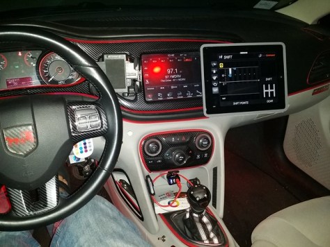
The center console has plenty of room for the cable, but I put the relay under the seat and secured it with ties – the two lines can go right underneath the center console trim with ease. You will need to drill a hole 13/16″ to accommodate the switch, but you can put it wherever you like. Here is mine:
20160131_003427
20160131_042144
20160131_042254
Finished install:
20160131_143710

It’s pretty easy to run the wire up the side of the center console, and over to the fuse box – there was plenty of wire to do so. I used the large metal bracket in the front, inside of the center console for a ground.

Go finish your beers and enjoy warmth! I have a Yukon with factory heated leather seats, and these heat up in half the time! I put mine on constant power, but I wouldn’t recommend that to others, as if it’s left in the high setting overnight, it will drop the battery voltage down to 10 volts -just below what it takes to start (I tested it) The reason I connected to constant is so if I am waiting in the car, and I don’t have the engine running, I can still have a fresh, toasty, Amish ass!!

Tags:

Ported Throttle Body

This damn car is like my extra girlfriend – I just get things squared away and it’s driving great, mileage is back up, then BAM!! I’m so frustrated, I just cleaned the throttle body, now I’m still getting strange revs up and down, inconsistent engine throttle, loss of engine rev in neutral, and idles up to 3000 RPM. I pulled the hot side pipe off of the throttle body and bought throttle body cleaner, but it looks like that’s not the issue. The thing is so clean I could eat off of it. I guess the stupid car needs a throttle body now. Shit!

At first, the throttle body error light would reset after a restart, now it will not. I guess it was going out slowly, much like my patience. My Corolla doesn’t do this crap, neither does my Yukon. Ugh. I guess I’m riding my bike all week. I cannot get any of my sockets to fit on this nut (the socket walls are too thick.) It is bigger than 10mm, seems like 7/16″ which doesn’t make any sense. I added the Cravenspeed Spacer last year, and it was the worst getting it off and on. Does that spacer come with different size nuts? Reading other posts, it seems like it was a T30 but mine is clearly not that. I can’t get the stupid nuts loose to save my life… Anyone want to buy a Dart?

OEM Throttle Body:20160805_083250
20160804_193944
20160805_180051

Replaced the throttle body. Interesting to note, the new part was ultra easier to work with from my original. The wrench and socket fit over the new TB just fine, and it was indeed a 7/16″ socket, which came with the Cravenspeed spacer. I put the MPB bored throttle body on as a replacement, as I got it used for cheaper than an unaltered OEM one. This did not fix the issue. I removed the accelerator pedal, still the same P2135 code. Taking it to the shop. (It was a wiring issue in the Unichip harness)

Tags:
Categories:

Headlights, Demon Eyes, Halo Headlights

Next Up: Headlights!!!! Woot Woot! Bake these bad boys for 10 minutes at 220˚ – Shazam! They open right up. Do not attempt with OEM Chrysler headlights, the adhesive is heat resistant and needs to be cut open.  Some aftermarket headlights may change the bulb socket, so be aware of that.  Mine are EagleEyes brand, and they now use an H8/H9/H11 bulb, instead of the Dart’s 9012 socket.
20150402_134325
20150605_082953
20150605_083002

OEM Silver Headlights:20150321_164658
20150405_201514

Painted the silver portion of the headlights gloss back, and also used the 2k Glamour Clear Coat. The pic also shows the demon eyes (partially) installed. I used a dremel to cut away enough of the headlight to fit the halo in, as I also used a diffuser, so you don’t see the naked LED strips.
20160706_004756
20160705_004624
20160709_094116
20160709_094127

I’ve got a lot of mods to do, if I want my build thread as long as @viperman96 … Lol. That being said, this project started as a simple repair. Last year, I installed my FMIC, and has been working great. A few weeks ago, I was taking a friend home after the Guns N’ Roses concert (BAD ASS, btw!) and on the way home, I heard a “pop.” I’m not sure what was up, but I was pretty sure something blew off. Sure enough, upon further inspection, my pipe blew off the driver’s side of the FMIC. DAMN!

I put her up on the Yoderian ramps, and had a look. I tried every form of yoga, stretching, contortion, and hypnosis, but I could not reach up into the area to fix it. At that point, I said screw it, and pulled the fascia off. I wasn’t ready to do the headlights, and other wiring I had been putting off, but at this point, I didn’t want to keep pulling it off. Once I got in there, I realized the hood latch bolts had come loose, and the FMIC fell forward just enough to pull it loose. I re-bolted it and used toothed lock-washers. That thing will never come out, again.

Here are some pics of the wire mess before I cleaned everything up. I went through an soldered, crimped and waterproofed every single connection. I also soldered on loop fasteners to all of the ground points. I even sanded down a few areas to make more solid ground connections. This proved to be totally worth it, as the cheap HIDs that used to flicker (just a tad) were now completely solid. Perhaps this is the only case of flawless, non-canbus lights, that I have seen, although it’s taken me a bit to finally get them perfect.

soldering the connections:20160706_004651

adding loop fasteners to the ground points:20160706_203116

Moved the (hot) resisters to below the intake and fascia, routed wires to the underbody lights:20160706_004708
20160706_004715

OMG – what a mess!20160706_004651

re-routed all of the wires under the fuse box (had to remove it):20160706_004738

added tie wraps (replaced them with black, later):IMG_20160708_170415

tie wraps (again, I could see the yellow through my grille, so I swapped them with black (doh!):20160706_203105

Almost back together:20160708_081451

Since I swapped out the battery for an Optima, it gave me the chance to put all of the auxiliary power on the side terminals, leaving only critical engine components on the top terminals. I may add a dry cell battery for car shows, as well.20160708_081506

After the front end was re-assembled, I put all of the control boxes along the passenger side under the hood. There is a ledge with plenty of space – All of the boxes got adhesive promotor and 3m adhesive. They are all RF controlled, and when the hood is open, I can read what mode / setting they are in, and adjust accordingly, if needed. This now includes the Starry Night Halos (https://www.starrynighthalos.com/ or Herculeds. The most powerful name in LED lighting.) Demon Eyes* and Yoderian Magical Underbody Lights.

[IMG] Angel Eyes, also known as “halos,” are accessory lights that are installed or integrated into a vehicle’s headlight assembly, to encircle the low or high beam headlight. They do not replace the headlight or any other lights, they are simply accessory lights, for cosmetic purposes, or to be used as a DRL.[/IMG]

These are the wires coming out of the headlights. All of the connections were waterproofed, as well, which I highly recommend. The Starry Night Halos DO NOT come with enough cable length to mount in a logical position, which was really annoying. I had to solder extensions on them.

20160708_200123

Here is the headlight assembled. You can see the halo diffuser in this pic with the lights off.
20160912_082714
20160812_211826
20160825_225642
IMG_20160824_235739

Here are all of the interior switches – the four colored switches are for interior and exterior lights.  The smaller, metal switches are Grille/Underbody Lights, SN Halos, and Demon Eyes, respectively.

20160701_171357
20160710_204820
20160710_212400
20160712_224843
20160715_200821
I would also like to point out to the next guy trying this – the Dragon Laminates (Dragon Eyes) baked in the oven @ 220˚ for 10 minutes with no issues, whatsoever.

*Angel Eyes, also known as “halos,” are accessory lights that are installed or integrated into a vehicle’s headlight assembly, to encircle the low or high beam headlight. They do not replace the headlight or any other lights, they are simply accessory lights, for cosmetic purposes, or to be used as a DRL.

Tags:

Painted Door Handles and Rear Diffuser Fins

Plasti dip is not a mod!! So… I ripped all of the plasti dip off of my black door handles, and pulled them off the car again. This time, I rough sanded them down, then applied a few coats of adhesive primer, followed by two coats of primer, and then finally, several coats of black, high-gloss paint. The paint is specifically designed for plastic and automotive use. This is the final coat, drying in my backyard.

20160702_175251v

Here are the handles, lock, and rear diffuser fins after the final clear coat. I used industrial strength, professional clear coat, called 2k Clear Glamour. Keep in mind, this stuff is so powerful, it has to be opened and used within 48 hours, or the clear coat will harden in the can. Just to be safe, I allowed the paint to cure for 3 days (72 hours) and then let the clear coat cure for another 3 days before re-installing them on the car. My wife doesn’t usually make comments about my craziness (car mods) but even she said they looked amazing back on the car. I’d have to agree – well worth the wait!!

20160706_004559

20160706_004614
20160822_224434Here is where I got the clear coat – a bit pricey, but worth it!

Clear Coat Link

Tags:

LED Lighting, Dream Color Underglow Lighting, Wheel well Lighting, Strobe Lights

Started out with blowing off one of my pipes connecting the FMIC – before I knew it, she looked like this, again:20160706_004651

Next installment, interior switches and wiring. I ran all of the needed wires through the firewall, both below the clutch, as well as on the passenger side, behind the glove box. I did the project in phases, as there is never much time in my life, nowadays. I pre-wired all of the switches in my shop, and measured out all of the cable runs, leaving the excess at the interior firewall. Most of the wires could be run by simply removing the lower footwell panels and below the steering column. Here are the pre-wired switches, and the holes already drilled out. Everything was trimmed and heat-shrinked prior to the installation in these pics:
20160701_171404
20160701_171357

The wiring is a bit more complicated than needed for most, but it is my specialty, and this is for car shows and hang-outs. The first four colored switches are simple on/off, controlling the strobe lights outside, the KITT LED lights, interior roof shadow lights, and the console and glove box lighting. The second set of switches are DPDT switches, or on-off-on. These are wired to two separate power sources. Up is on constant, with power straight from the battery. Middle position is off, and the lower position is on with an ignition switched fuse location. This enables the exterior LED lights, and the Halo headlights and demon eyes to come on with the car, but also enables them to run with the car off and locked.

Tags:

Electric Exhaust Cutout and Custom Midpipe / B-pipe

Exhaust cutout installed today!  This is an electric cutout, that dumps straight out of my down pipe, and then to a custom 2.5″ midpipe / B-pipe.  Switch is installed next to shifter.Name: ForumRunner_20160606_102413.png Views: 112 Size: 406.7 KB

I had a custom 2.5″ B-pipe created, and welded on a cutout, right after the downpipe. I installed the switch inside, near the shifter, but out of the way of the seat. Only takes a second to open and close – sounds awesome! It moves the power band up, so the turbo kicks in smoother, and screams up top. There is a little bit of low end torque lost, similar to those with a 3″ exhaust, but makes it up above that. I wish the pics were a bit better, but whatever. It exits out of the front hole / door in the underbody aero panel. It was open for over a full tank of gas, no issues. I was going to add a tip, but it’s too low.
20160606_104615
20160606_104625
20160606_104639
20160606_125032
20160530_135252

I cut this out for a tip, but never installed it. #lowlife  The above hole was later cut a bit larger, as I sometimes shoot flames!
20160627_215417
20160627_215434

This is how I soldered the switch. This switch is a momentary on/off/on switch. Forward is open, back is piped exhaust, tied to ignition switched power.
20160701_171351

I purchased the electric cutout kit from ebay, and it was about $85.  Here is something similar.  It is a basic 2.5″ cutout, that includes cutout, switch, wire, gaskets, y-pipe, clamp, dump, and hardware.  The midpipe is fine, running closed, for emissions in IL.  The high flow downpipe, however, was not, and has to be removed every two years to pass emissions.

Here is the final installation pic – It is the silver switch, to the left of the gear shifter:20161010_224301

No codes, or issues, however, if you run the cutout open for a long time, especially under WOT, you may get an error for rear O2, although it hardly comes on for me.  I ran her on the dunk, and open and closed was very close, although open gained 2-3 more whp.

Tags:

Rear Engine Mount

Most guys have done this first, I guess, but I was hesitant to do it, but it’s not bad. There is a bit more vibration, especially when the AC is running at idle, but I found out the sound system has an off switch! Once I had the music back on, couldn’t tell the vibes unless AC on at idle. I do feel the wheels spin easier, and seems to be more responsive. At the same time I did the rear engine mount (flex, in orange) I also did the CDV delete. My full review of that is here.

This is the stock OEM mount next to the Deyeme Racing Flex mount:20160530_133544
20160530_133136
20160530_134807
20160530_135244
20160530_135259

Tags:
Categories: